


 |
|
EMA3D Graphical User Interface - CADfix
The Graphical User Interface for EMA3D consists of CADfix, a CAD-CAE application produced by ITI Transcendata Ltd. (formerly FEGS Ltd.) of Cambridge, UK, augmented by an EMA developed tool set. It provides world class pre-and post-processing functionality with the following capabilities:
- Model building from CAD file import and/or from scratch using keyboard/mouse
- Extensive CAD file repair and processing facilities.
- Extensive CAD-like model building capability
- Geometry primitives that speed model building
- Creation and export of IGES and other CAD files
- Automatic mesh generation
- Open framework architecture
- Setup of EMA3D simulation with interactive GUI tools
- Individual user customization via Tcl/Tk
- Light source shading
- X, GL, VGL and Open GL drivers
- Rotation, zoom, and position by mouse
- Visualization of sections or parts of models and meshes
- Visualization
- Geometry, mesh, nodes, material properties, results
- Time and frequency domain plots
- False color surface plots
- Deformed contour surface plots
- Animations in time or frequency domains. Animations can also be rotated and zoomed with the mouse while in process.
- Streamlines
CADfix Usage with EMA3D
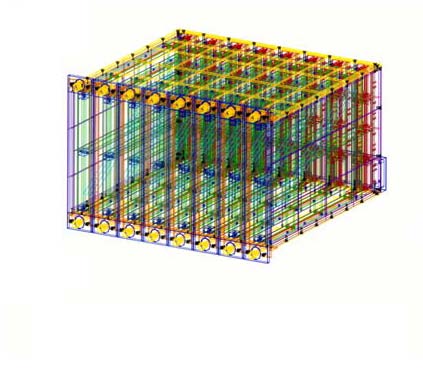 |
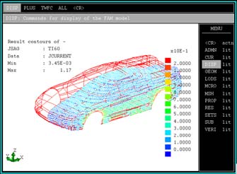
The user can either build models directly in CADfix or can import the geometry from CAD files formats such as IGES and STEP, and from several other CAD systems. The electronic enclosure shown here was imported from IGES files. CADfix simplified the geometry to produce an analysis model that was used for intra-system EMC simulations. The coupling to other internal PCBs from a clock pulse source on another PCB was evaluated. The coupling is visualized at right. |
 |
 |
 |
 |
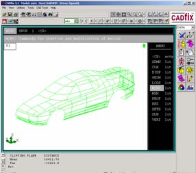
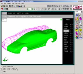
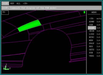
| Simulation begins with creating geometry, which can be done by the GUI modeling capabilities, or by import of CAD files as shown here. |
The CAD file only had the left half; the right half was easily created by the GUI using a reflect command. There are 500 surfaces in this model. |
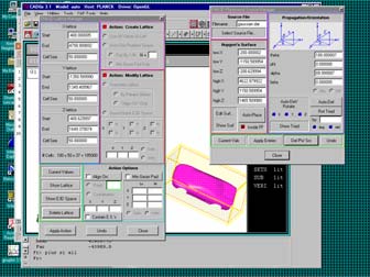
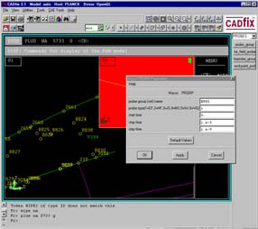
GUI tools such as the lattice manager and plane wave manager make it easy for the user to set up the problem. |
 |
 |
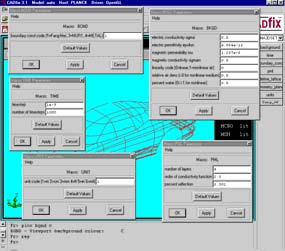 |
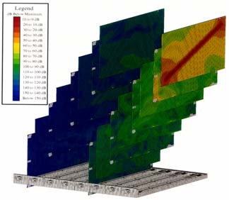
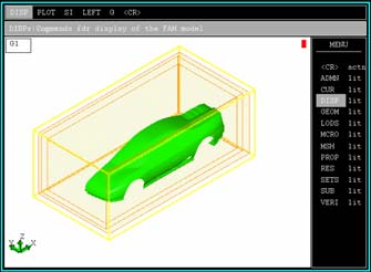
| This shows 4 surfaces from outside in: lattice boundary, problem space boundary, far field integration surface, and the Huygens’ surface. |
A wire harness was added to the model by the GUI. Material properties, such as the thin wire property, are created and assigned to objects. |
Other GUI tools set up problem parameters. Note that background color can be changed. |
 |
 |
 |
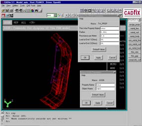
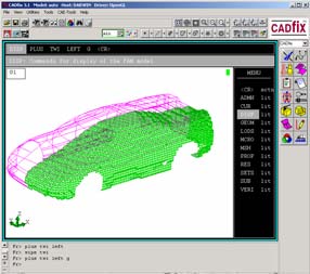
| Meshing is done by a single mouse click. The mesh of any part can be individually visualized. |
Any part can be selected and visualized. Material properties of any part can be assigned and visualized. |
Any number of view ports can be created to show various problem aspects, such as node numbers on a single surface, and on the wire harness. |
 |
 |
 |
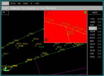
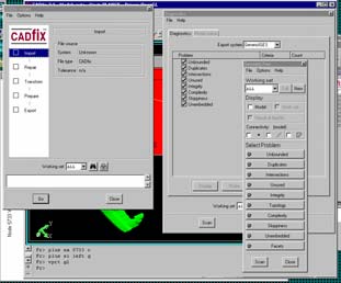
| Results are stored in probe groups, consisting of sets of nodes, created by the GUI. |
CADfix has considerable capability to import, scan, and automatically repair geometry, as shown by these GUI tools. |
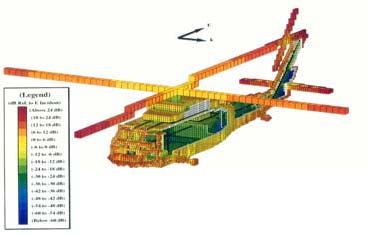
Time or frequency domain results can be overlaid on the geometry or the mesh for visualization. Animations are easily made from such plots. |
Additional CADfix Information
ITI Transcendata Ltd. Web Site
CADfix Home Page on ITI Transcendata Web Site
CADfix CAE Home Page on ITI Transcendata Web Site*
*CADfix CAE is the editon of CADfix used as the GUI and front-end for EMA3D. CADfix CAE is geared towards finite element or finite difference analysis; other editions of CADfix are used more for CAD translation, repair, integrity checking, and other CAD interoperability issues.
Continue with EMA3D Brochure
Proceed to Obtaining Frequency Domain Results
|